Context
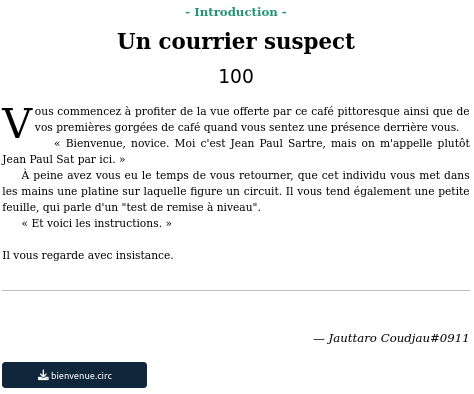
We are given the “bienvenue.circ” file.
Resolution
Looking at the net, CIRC is a file extension commonly associated with Logisim Circuit files. This kind of file is used by “Logisim” software.
We download the software (I chose the java version to not have problems on my VM) and we run it.
1
java -jar logisim-generic-2.7.1.jar &
We open the “bienvenue.circ” file (File > Open)
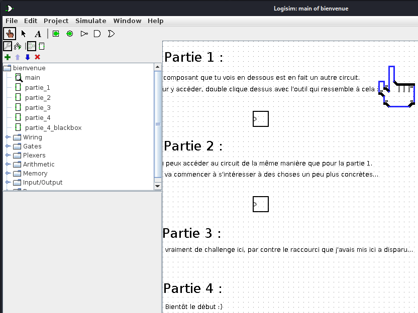
We end up on the main page.
There are 4 parts in this challenge. It’s an introduction so we guided to use the software.
Part 1
We just need to go on the tab “partie_1”.
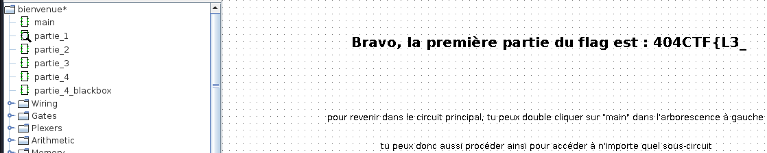
The flag begins with: 404CTF{L3_
Part 2
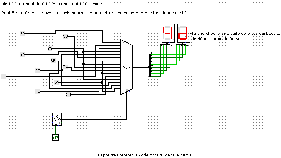
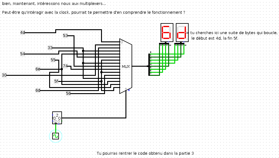
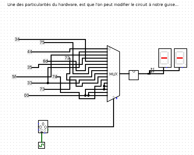
This part wants us to understand what a MUX is.
A multiplexer, often referred to as a “MUX,” is a digital circuit that combines multiple input signals into a single output signal. It selects one of the input lines based on the control inputs and forwards that selected input to the output. The control inputs determine which input line is active and which data gets transmitted.
The basic structure of a multiplexer consists of:
Input lines: These are the data lines that carry the input signals. The number of input lines determines the number of inputs that can be connected to the multiplexer. These are the lines on the left of the MUX.
Control inputs: These inputs determine which input line is selected. The number of control inputs determines the number of selection options available. In our case this is the line at the bottom of the MUX.
Output line: This is the line where the selected input signal is transmitted. This is the line at the right of the MUX
So, in order to have the value of the 3rd line transmitted to the output, we need to input 3 in the control inputs.
Example the third input line (index 2) has a value of ‘6d’. If we input 2 in the control line, we get ‘6d’ outputed.
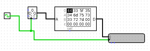
Part 3
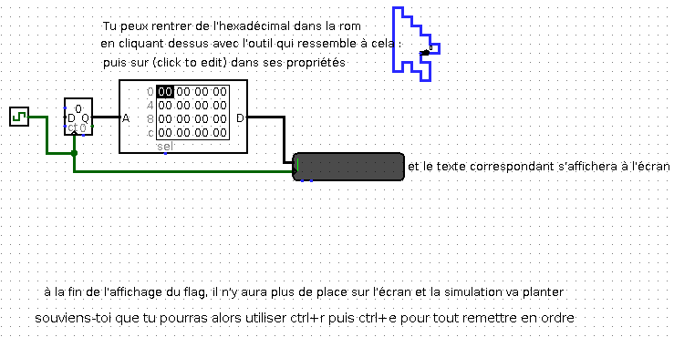
This part is related to the second part. We have to get the values of the inputs lines of the MUX in the part 2 and report it on the ROM.
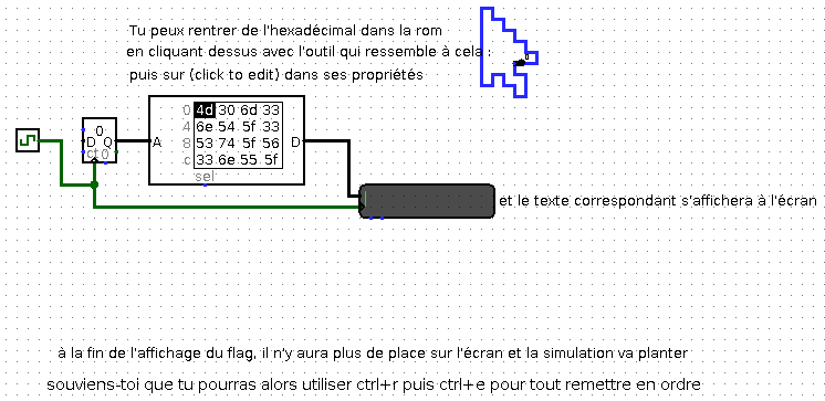
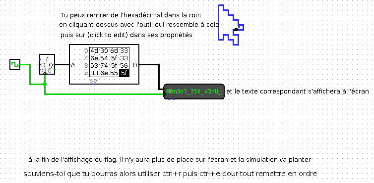
Running ticks on the clock, we get the second part of the flag.
Part 4
In part we are given this MUX:
We can reproduce what we did earlier with part 2 and part 3 to get the flag
We run the clock and we have got it 😁
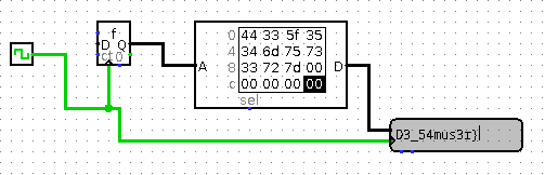
We concatenate our flag’s fragment: 404CTF{L3_M0m3nT_3St_V3nU_D3_54mus3r}
The part 4 was not meant to be done that way I think. The idea was more to implement the blackbox in order to reproduce how the part 3 works and get the circuit with the MUX to work and display the flag.
I hope you enjoyed this writeup and learned something 😊 !